
 France
 Germany
 Spain
Spain Netherlands
 Italy
Italy Hungary
 United States
 Australia
What is an RTD Sensor? - Information on RTD Temperature Sensors
An RTD sensor is a type of temperature sensor that changes resistance in response to temperature changes. Usually a 100 ohm platinum element is used where the relationship between resistance and temperature is standardised and repeatable. RTDs are passive, meaning they do not generate an output on their own but use electronic devices (indicators) to measure the sensor's resistance by passing a small current (typically 1mA) through the sensor, which in turn generates a voltage. The resistance of the sensor increases as the temperature increases and are provided in our resistance vs temperature tables.
RTD is simply an acronym of Resistance Temperature Detector, a type of resistance thermometer (usually Pt100) used for a wide variety of temperature measurement applications. RTD sensors are also referred to as Pt100 Sensors and PRTs. There are many styles of RTD Sensor and typically they are Pt100, although Pt1000 is also popular, both are available in a wide range of designs and constructions.
How do RTD Sensors work?
RTD Sensors, usually Pt100, rely on a resistive element with a resistance of 100ohms at 0ºC. This element is generally encased in a stainless steel sheath suitable for most temperature measurement applications. As the temperature changes the value of this resistance also changes providing a reliable and predictable resistance value which can then be measured and converted to display in ºF or ºC by appropriate instrumentation.
RTD Sensors are reliable and accurate especially when higher grade elements are selected. A full explanation of the working principles of RTD sensors is detailed below.
What is the difference between 2-wire, 3-wire and 4-wire RTD Pt100 Sensors?
When connected as a 2 wire system the resistance of the 2 wires connecting the RTD sensor to the instrument will be included in any measurement, thus introducing an error equivalent to this lead resistance. A 3 wire RTD Sensor will (via bridge networks) compensate for one leg of this lead resistance and a 4 wire system will compensate for both leads.
A full explanation of the working principles of RTD sensors is detailed below.
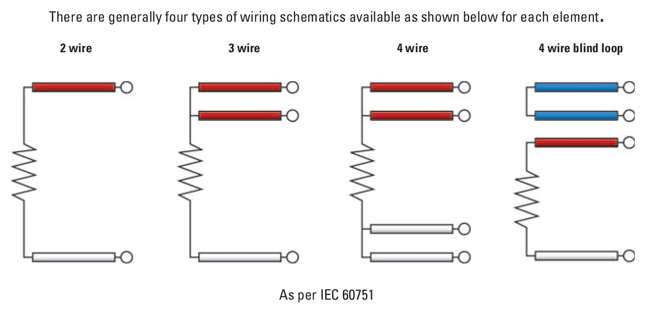
What is the colour code and wiring configuration for RTD Pt100 Sensors?
2-wire RTD Pt100 Sensor = 1 x red wire and 1 white wire
3-wire RTD Pt100 Sensor = 2 x red wires and 1 white wire
4-wire RTD Pt100 Sensor = 2 x red wire and 2 white wires
A colour code and wiring diagram is shown below.
For a detailed explanation of RTD wiring and bridge networks, please click here.
Typical RTD Sensors - Temperature Sensors
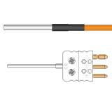
Mineral InsulatedRTD Sensors
 Our most popular style of RTD sensor and ideal for most applications. Vast choice of terminations e.g. pot seals, cables, connectors, heads etc.
Rigid Stem
Our most popular style of RTD sensor and ideal for most applications. Vast choice of terminations e.g. pot seals, cables, connectors, heads etc.
Rigid StemRTD Sensors
 Ideal for rigid stem applications or where the sensor is shorter than 50mm, limited to 250°C. Wide choice of terminations
Hand Held
Ideal for rigid stem applications or where the sensor is shorter than 50mm, limited to 250°C. Wide choice of terminations
Hand HeldRTD Sensors
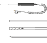 A range of hand held RTD Sensors to suit a variety of applications from general purpose to surface and air temperature measurements
RTD Sensors for
A range of hand held RTD Sensors to suit a variety of applications from general purpose to surface and air temperature measurements
RTD Sensors forSurface Measurements
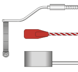 A wide range of RTD sensors for surface measurements including self adhesive patch, pipe, magnetic etc.
RTD Theory
The resistance that an electrical conductor exhibits to the flow of an electric current is related to its temperature, essentially because of electron scattering effects and atomic lattice vibrations. The basis of this theory is that free electrons travel through the metal as plane waves modified by a function having the periodicity of the crystal lattice. The only little snag here is that impurities and what are termed lattice defects can also result in scattering, giving resistance variations. Fortunately, this effect is largely temperature-independent, so does not pose too much of a problem.
In fact, the concept of detecting temperature using resistance is considerably easier to work with in practice than is thermocouple thermometry. Firstly, the measurement is absolute, so no reference junction or cold junction compensation is required. Secondly, straightforward copper wires can be used between the sensor and your instrumentation since there are no special requirements in this respect.
The first recorded proposal to use the temperature dependence of resistance for sensing was made in the 1860’s by Sir William Siemens, and thermometers based on the effect were manufactured for a while from about 1870. However, although he used platinum (the most widely used material in RTD sensor types today), the interpolation formulae derived were inadequate. Also, instability was a problem due mainly to his construction methods - harnessing a refractory former inside an iron tube, resulting in differential expansion and platinum strain and contamination problems. Callendar took up the reins in 1887, but it was not until 1899 that the difficulties were ironed out and the use of platinum resistance thermometers was established.
It is now accepted that as long as the temperature relationship with resistance is predictable, smooth and stable, the phenomenon can indeed be used for temperature measurement. But for this to be true, the resistance effects due to impurities must be small - as is the case with some of the pure metals whose resistance is almost entirely dependent on temperature. However, since in thermometry almost entirely is not good enough, the impurity-related resistance must also be (for all practical purposes) constant such that it can be ignored. This means that physical and chemical composition must be kept constant. An important requirement for accurate resistance thermometry is that the sensing element must be pure. It must also be (and remain) in an annealed condition, via suitable heat treatment of the materials such that it is not inclined to change physically. Then again, it must be kept in an environment protected from contamination so that chemical changes are indeed obviated.
Meanwhile, another challenge for the manufacturer is to support the fine, pure wire adequately, while imposing minimum strains due to differential expansion between the wire and its surroundings or former - even though the sensors may be attached to operating plant, with all the rigours of this characteristically arduous environment. Depending upon the accuracy you are after, the relationship governing platinum resistance thermometer output against temperature follows the quadratic equation:
Rt /R0 = 1 + At + Bt2
(above 0°C this second order approach is more than adequate)
or Rt /R0 = 1 + At + Bt2 + Ct3 (t-100)
(below 0°C, if you are looking for higher accuracy of representation, the third order provides it).
Therefore:
t = (1/α)(Rt - R0)/R0 + δ(t/100)(t/100 -1)
Where: Rt is the thermometer resistance at temperature t; R0 is the thermometer resistance at 0°C; and t is the temperature in °C. A, B and C are constants (coefficients) determined by calibration. In the IEC 60751 industrial RTD standard, A is 3.90802 x 10⁻³; B is -5.802 x 10⁻⁷; and C is -4.2735 x 10⁻¹². Incidentally, since even this three term representation is imperfect, the ITS-90 scale introduces a further reference function with a set of deviation equations for use over the full practical temperature range above 0°C (a 20 term polynomial). The a coefficient, (R100 - R0)/100 . R0, essentially defines purity and state of anneal of the platinum, and is basically the mean temperature coefficient of resistance between 0 and 100°C (the mean slope of the resistance vs temperature curve in that region). Meanwhile, δ is the coefficient describing the departure from linearity in the same range. It depends upon the thermal expansion and the density of states curve near the Fermi energy. In fact, both quantities depend upon the purity of the platinum wire. For high purity platinum in a fully annealed state the a coefficient is between 3.925x10⁻³/°C and 3.928x10⁻³/°C.
For commercially produced platinum resistance thermometers, standard tables of resistance versus temperature have been produced based on an R value of 100 ohms at 0°C and a fundamental interval (R100 - R0) of 38.5 ohms (α coefficient of 3.85x10⁻³/°C) using pure platinum doped with another metal. The tables are available in IEC 60751, tolerance classes A and B.
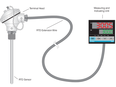
A Typical Industrial RTD Sensor
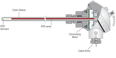
Typical RTD Probe Construction - Probe and Head
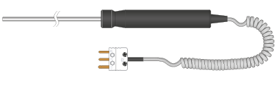
Hand Held RTD Probe
Bridge Measuring Systems - RTD Sensors
Commercially available industrial bridge measuring systems use one of several circuit arrangements relying mainly on two versions of the Wheatstone bridge - balanced, or fixed bridge, both resistive. Incidentally, it is worth just noting that inductive ratio bridges can also be used, in which precision wound transformers are used for the ratio arms of the bridge. These can offer several advantages in terms of robustness, portability and stability.
Returning to resistive bridges, whatever the circuit format selected, all bridges can be made self-balancing using servo mechanisms controlled from the balance detector. In industrial applications, the bridge is not normally balanced (by altering variable resistances). Instead, as stated above, the imbalance voltage in a fixed element bridge tends to be used as a measure of the sensor resistance - and hence of temperature.
Irrespective of bridge style, all the bridge resistors, except, of course, the sensor, are set to exhibit negligible resistance change with temperature, and in AC bridges are designed to be non-inductive. Also, bridge arm resistance errors due to sliding contacts on variable resistors (where applicable) are normally prevented by introducing these into the current supply line itself, or the balance detector circuit where they can clearly have no influence on the bridge balance.
The sensing resistor, which may well be some distance away from the bridge in industrial applications, is then attached to the bridge using copper cable - whose resistance is low compared with that of the bridge, but which will obviously vary with temperature, particularly nearer to the measurement point. When the conductors are long, or of small cross section, these resistance changes can be large enough to cause significant errors in the temperature reading. There are several wiring configurations to compensate for this potential problem.
Two Wire RTD Sensor Configuration
The simple two wire connection shown in Figure 3.1 is used only where high accuracy is not required - the resistance of the connecting wires is always included with that of the sensor, leading to errors in the signal. In fact, a standard restriction with this arrangement is a maximum of 1 - 2 ohms resistance per conductor - which is typically about 300 feet of cable. This applies equally to balanced bridge and fixed bridge systems. The values of the lead resistance can only be determined in a separate measurement (without the RTD sensor) and therefore a continuous correction during the temperature measurement is not possible.
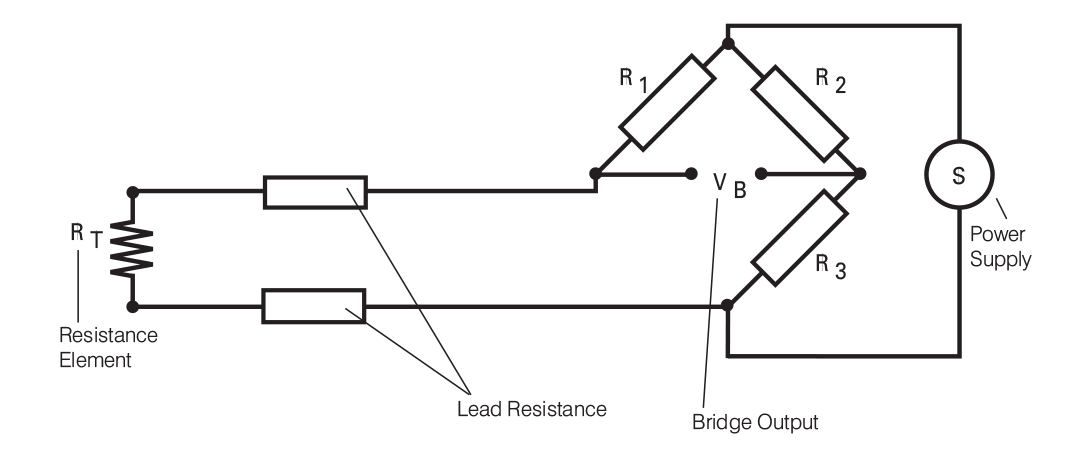
Figure 3.1: Wheatstone Bridge with RTD in Two Wire Configuration
Three Wire RTD Configuration
A better wiring configuration is shown in Figure 3.2. Here, the two leads of the sensor are on adjoining legs. Although there is lead resistance in each leg of the bridge, the lead resistance is cancelled out from the measurement. It is assumed that the two lead resistances are equal, therefore demanding high quality connection cables.This allows an increase to 10 ohms - usually allowing cable runs of around 1500 feet or more, if necessary.
Also, with this wiring configuration, if fixed bridge measurement is being made, compensation is clearly only good at the bridge balance point. Beyond this, errors will grow as the imbalance increases. This, however, can be minimized by using larger values of resistance in the opposite bridge circuits to reduce bridge current changes.
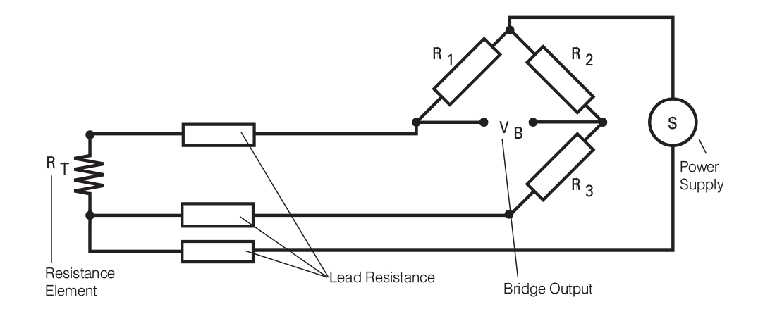
Figure 3.2: Wheatstone Bridge with RTD in Three Wire Configuration
Four Wire RTD Sensor Bridge Configurations
However, this approach is a little more costly on the copper wiring. An alternative, better version of the four wire configuration uses full four wire terminal RTDs, and as depicted in figure 3.4. This provides for full cancellation of spurious effects with the bridge type measuring technique. Cable resistance of up to 15 ohms can be handled with this arrangement, accommodating cable runs of around 3,000 feet. Incidentally, the same limitation as for three wire connections applies if the fixed-bridge, direct-reading approach is being used.
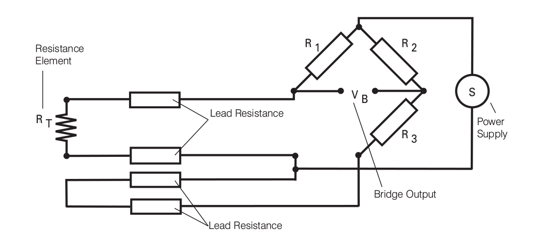
Figure 3.3: Wheatstone Bridge with RTD in Four Wire Configuration
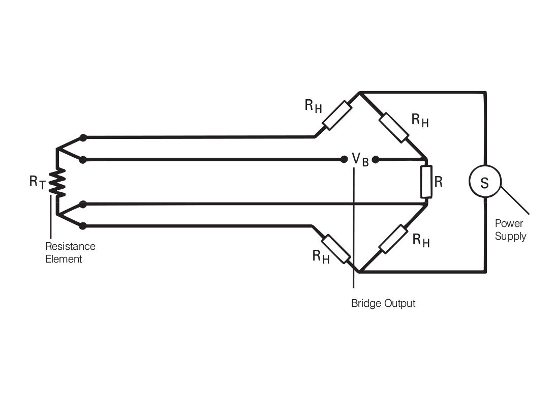
Figure 3.4: Alternative Four Wire Bridge Connection