
 France
 Germany
 Spain
Spain Netherlands
 Italy
Italy Hungary
 United States
 Australia
Averaging Thermocouples and RTDs
Contents
Thermocouples can be arranged so that their combined outputs provide an average temperature reading. This can be done through physical wiring methods such as parallel or series connections.
Thermocouples in Parallel
Connecting thermocouples in parallel allows their outputs to combine into an average voltage, but for this to work reliably:
- Loop resistance between each thermocouple's measuring junction and the common connection must be matched.
- This is typically achieved by using thermocouples of the same construction and length (see Figure 6.1).
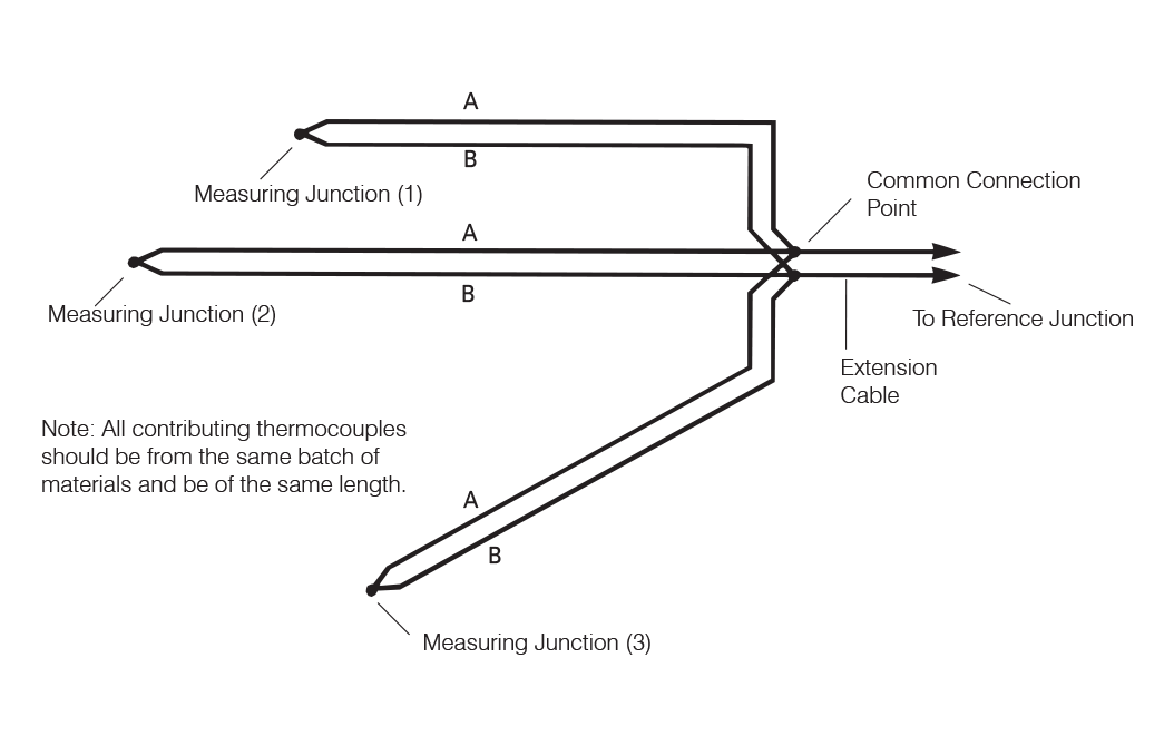
Figure 6.1: Thermocouples in Parallel
Circuit Balancing with Resistors
Another approach involves adding resistors to balance each leg of the thermocouple circuits (see Figure 6.2).
- If used, it's best to make these resistors from matching thermocouple materials.
- If using conventional resistors, insert them into the copper leads and choose materials with thermoelectric properties close to copper.
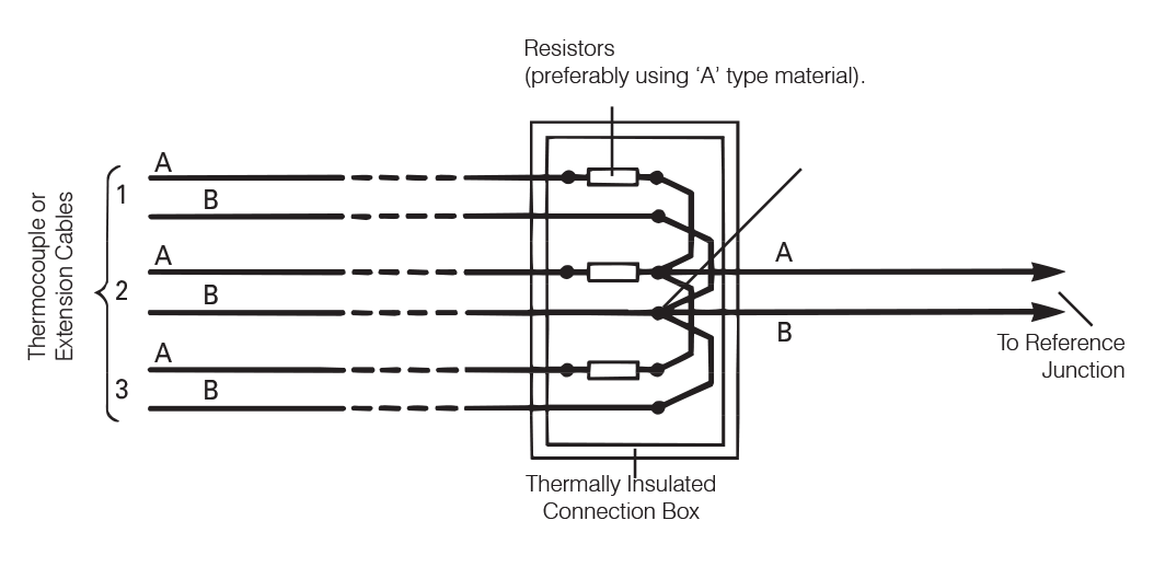
Figure 6.2: Circuit Balancing using Resistors
Ideal Case: Dual Resistors
The ideal configuration includes two resistors of equal value—one in each side of the copper loop (see Figure 6.3). This helps cancel out spurious thermal voltages.
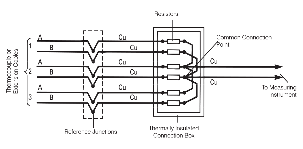
Figure 6.2: The Ideal Case - with Dual Resistors
Practical Considerations
- Thermocouple outputs are not perfectly linear; variations in thermoelectric properties and resistance changes with temperature can affect accuracy.
- All measuring junctions must be electrically isolated to avoid parallel conduction paths.
- Added resistors should be housed in a thermally stable enclosure to prevent unintended temperature effects.
Tip: To measure loop resistance accurately, use a low-frequency AC bridge. Thermoelectric voltages can distort readings with DC instruments. Always check by reversing the polarity to detect such effects.
Thermocouples in Series
Thermocouples can also be connected in series for averaging:
- Each sensor requires its own reference junction.
- The output voltage is the sum of individual thermocouple voltages.
- The average temperature is then calculated by dividing this total by the number of thermocouples.
Since no significant current flows in a voltage-measurement setup, circuit resistance isn’t critical. However, care must still be taken to:
- Maintain electrical isolation between junctions.
- Account for sensitivity changes with temperature.
Digital Averaging and Data Logging
Digital systems, such as data loggers or smart instruments, can average temperature readings in real-time or during later data processing. This method offers several advantages:
- No need to physically modify thermocouple or RTD circuits.
- Enables real-time or post-processed averaging.
- Allows weighting of sensors or exclusion of faulty data (e.g., from a degrading thermocouple).
RTDs and Averaging
Unlike thermocouples, RTDs (Resistance Temperature Detectors) don’t easily support hardware averaging due to the nature of resistive measurement:
- RTDs measure voltage drop across a resistance, often using a Wheatstone bridge or current source.
- A practical solution is to energize multiple RTDs from a shared constant current source and switch between them digitally.
- The average temperature is then computed by digital processing in the connected instrument.
For simpler applications, the stem sensitivity of RTDs can provide natural averaging along the probe’s length — the overall resistance change reflects an averaged temperature across the stem.
i Many RTD assemblies are also available in duplex or triplex formats, making them suitable for area-based averaging.
Summary
Thermocouples support physical averaging via parallel or series wiring, though matching resistances and isolating junctions are essential. Digital averaging using a data logger or instrument is often easier and more accurate.
RTDs are less suited to hardware averaging but can be averaged using shared current sources and digital switching. Stem sensitivity and multipoint assemblies also offer practical averaging for industrial applications.
Note: The information in this guide is provided for general informational and educational purposes only. While we aim for accuracy, all data, examples, and recommendations are provided “as is” without warranty of any kind. Standards, specifications, and best practices may change over time, so always confirm current requirements before use.
Need help or have a question? We’re here to assist — feel free to contact us.
Further Reading
RTD vs Thermocouple – Choosing the Right Sensor
Explore the features and characteristics of thermocouples and RTDs
RTD Output Tables
View Resistance versus Temperature tables for all Pt100 sensors.
What are the RTD colour codes?
Explore RTD colour codes and wiring configurations.