
 France
 Germany
 Spain
Spain Netherlands
 Italy
Italy Hungary
 United States
 Australia
RTD Element Designs
Contents
Resistance Temperature Detectors (RTDs) can be constructed in a variety of ways depending on the measurement environment. From precision laboratory devices to rugged industrial assemblies, design choices impact accuracy, durability, stability, and cost. Below is a summary of the most widely used RTD element constructions, starting with laboratory-grade designs.
Laboratory RTD Designs
Laboratory RTDs prioritize precision and stability. These elements are carefully constructed to minimize strain on the sensing element and maintain excellent calibration over time.
Precision Coil-in-Tube Designs
In modern standards laboratories, the most accurate RTD elements are constructed using:
- Fine platinum wire (typically 0.07 mm in diameter).
- Helically wound and friction-mounted inside silica, glass, or alumina tubes.
- Four-wire configurations for high-accuracy resistance measurement (see Figure 6.1).
- Hermetically sealed and backfilled with argon or air/oxygen to ensure an oxidizing environment for the platinum.
- Lead wires are carefully insulated with mica, silica, or sapphire to maintain high insulation resistance and minimize leakage.
These assemblies allow the platinum to expand and contract freely, ensuring long-term stability above –189°C.
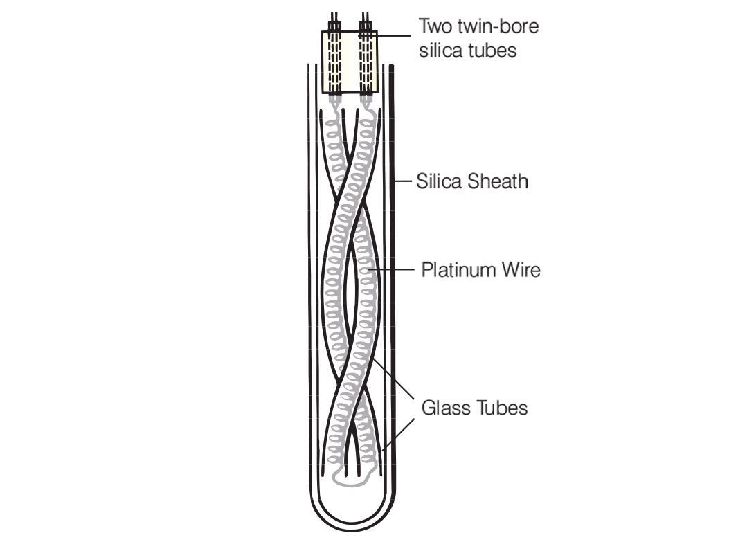
Figure 6.1: Traditional laboratory style RTD sensor
Cryogenic Capsules
At very low temperatures, capsule RTDs are preferred. These compact designs:
- Use thin-walled platinum tubes filled with helium gas for excellent thermal conductivity.
- Typically measure around 50 mm in length and 5 mm in diameter.
- Are sealed and rugged, with very low thermal mass (see Figure 6.2).
Such designs are ideal for cryogenic calibration and ultra-low temperature measurement environments.
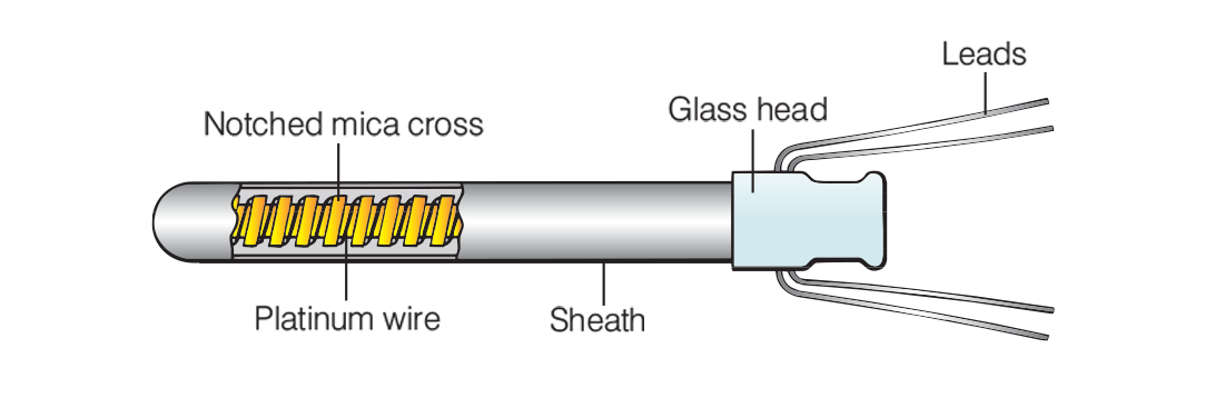
Figure 6.2: Capsule design platinum RTD
High-Temperature Reference Elements
For temperatures above 660°C, platinum RTDs face issues with insulation resistance and drift. To overcome this:
- Low-resistance RTDs are constructed using multiple platinum strands in parallel.
- Elements like the NBS “bird cage” design reduce lead wire resistance effects (see Figure 6.3).
- The lower resistance (e.g. 0.2 Ω at 0°C) makes them less sensitive to shunting by leakage currents, improving accuracy at elevated temperatures.
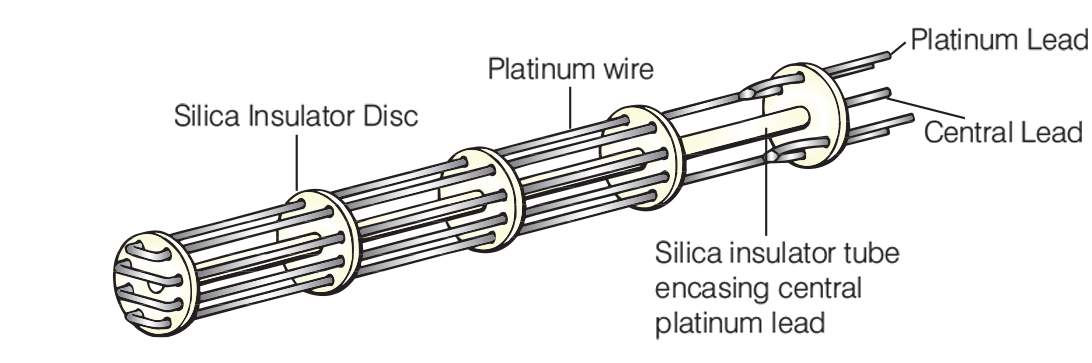
Figure 6.3: Bird cage high temperature RTD
Industrial RTD Designs
Industrial RTDs are built to survive in harsher environments, where vibration, thermal shock, and mechanical stress are common. These designs balance ruggedness with measurement stability.
Wire-Wound Ceramic Elements
Traditional industrial RTDs use ceramic or glass bobbins around which platinum wire is wound:
- The winding is sealed with ceramic cement or glass to hold it in place (see Figure 6.4).
- Ceramic rods with spiral grooves are another option, where wire is protected from vibration (see Figure 6.5).
These designs are robust but may sacrifice some freedom of expansion for the platinum element, which can affect long-term stability.
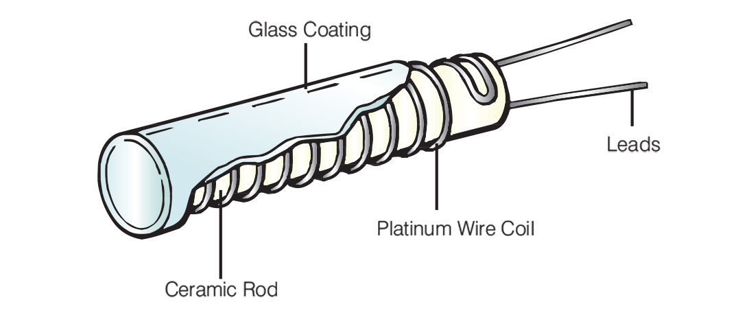
Figure 6.4: Classic cylindrical style industrial wire wound RTD
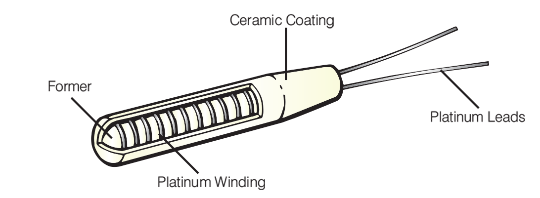 Figure 6.5: Cylindrical Sensor with Wire Coil set in Grooves
Partially Supported Coil Assemblies
A more advanced design uses partially supported platinum coils:
- The helical coil is inserted into a multi-bore alumina tube.
- Only certain contact points are fixed with glass, allowing the rest of the wire to move freely (see Figure 6.6).
- This design greatly improves vibration resistance while still minimizing strain.
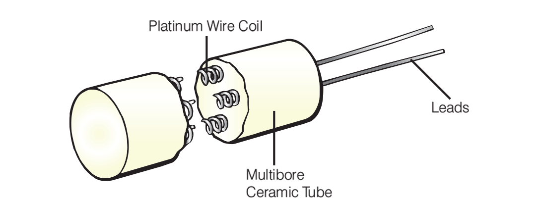
Figure 6.6: Partial Support using Multi-bore Alumina Tubing
Typical units are 25 mm long and around 3 mm in diameter. They are carefully trimmed to match 100 Ω at 0°C, ensuring conformity with IEC standards.
These are among the most stable industrial elements available, with drift as low as a few hundredths of a degree across the –200°C to +850°C range.
Film Thermometers
Film RTDs are a modern evolution in sensor design. Instead of using wire, these elements rely on thin or thick layers of platinum deposited on a substrate.
Thin Film Designs
- A very thin platinum layer is vacuum-deposited onto a ceramic substrate.
- Ideal for surface or air temperature measurements up to around 500°C.
- Fast response time due to low thermal mass and excellent resistance to vibration (see Figure 6.7).
Thick Film Designs
- Use platinum-glass pastes screen-printed onto a flat surface, then fired at high temperatures.
- More common in lower-cost or batch-production environments.
Pros and Limitations
-
Advantages:
- Highly repeatable batch production.
- Cost-effective with fast thermal response.
- Good vibration tolerance.
-
Limitations:
- Less long-term stability compared to wire-wound types.
- Platinum layer is small and subject to contamination.
- Mechanical strain during thermal cycling may affect calibration.
- Variability between batches may limit interchangeability.
While top-grade wire-wound RTDs can achieve ±0.005% stability, film elements generally offer ±0.05% - still sufficient for many industrial applications.
Summary: Choosing the Right RTD Element Design
| RTD Type | Temperature Range | Stability | Mechanical Strength | Typical Use |
|---|---|---|---|---|
| Laboratory Coil-in-Tube | –189°C to +660°C | Excellent | Low | Calibration labs, standards |
| Cryogenic Capsule | < –150°C | Excellent | Medium | Cryogenic measurement |
| High-Temp Low-Resistance | up to 1,000°C | High | Medium | High-temp industrial reference |
| Wire-Wound Ceramic | –200°C to +600°C | Good | High | General industrial use |
| Partially Supported Coil | –200°C to +850°C | Very High | High | Harsh industrial environments |
| Thin/Thick Film | –50°C to +500°C | Moderate | Very High | HVAC, appliances, surface sensing |
Note: The information in this guide is provided for general informational and educational purposes only. While we aim for accuracy, all data, examples, and recommendations are provided “as is” without warranty of any kind. Standards, specifications, and best practices may change over time, so always confirm current requirements before use.
Need help or have a question? We’re here to assist — feel free to contact us.
Further Reading
RTD vs Thermocouple – Choosing the Right Sensor
Explore the features and characteristics of thermocouples and RTDs
RTD Output Tables
View Resistance versus Temperature tables for all Pt100 sensors.
What are the RTD colour codes?
Explore RTD colour codes and wiring configurations.