
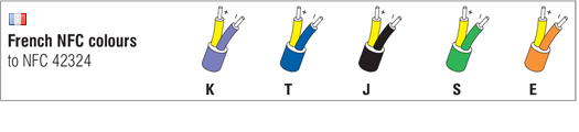
 France
 Germany
 Spain
Spain Netherlands
 Italy
Italy Hungary
 United States
 Australia
Thermocouple Extension and Compensating Cables – Tolerances and Identification (IEC 60584-3)
What is IEC 60584-3?
IEC 60584-3 defines the international standards for the identification, color coding, and tolerance of thermocouple extension and compensating cables. Unlike traditional thermoelement EMF reference to platinum, the standard is based on the thermoelectric EMF between conductors.
i Key Points:
- Identification and Colour Codes:
- Extension cables are marked with an 'X' after the thermocouple type (e.g., KX for Type K extension), and compensating cables with a 'C' (e.g., KC).
- Colour Codes: Each cable type is identified by specific colours for the insulation of the positive leg, with all negative legs being white. For example, Type K extension cables typically have green insulation for the positive leg.
- Important: The sheath, if present, follows the same colour as the positive leg, except in intrinsically safe circuits, where it is always blue.
- Tolerances:
Tolerances define the maximum additional error introduced by the cable, measured in microvolts (µV). For example: - KX Class 1 (Type K Extension Cable) has a tolerance of ±60µV between -25°C and +200°C, equivalent to about ±1.5°C at temperatures above 0°C.
- JX Class 1 (Type J Extension Cable) provides tighter control than the standard Class 2.
Thermocouple Cable Tolerances
While colour coding does not differentiate grades of compensating materials, the materials themselves have important differences as shown in table 3.4. (RCB/SCB has largely replaced RCA/SCA, meaning one alloy now serves for both Type R and Type S compensating cables.):
| IEC 60584-3:2007 | ANSI MC96.1 1975 | |||||
|---|---|---|---|---|---|---|
| Type | Class 1 | Class 2 | Class 1 | Class 2 | Alloy Combination | Cable Temperature (in ºC) |
| JX | ±1.5 | ±2.5 | ±1.1 | ±2.2 | Iron/Constantan | -25 to 200 |
| TX | ±0.5 | ±1.0 | ±0.5 | ±1.0 | Copper/Constantan | -25 to 200 |
| EX | ±1.5 | ±2.5 | ±0.85 | ±1.7 | Nickel Chromium/Constantan | -25 to 200 |
| KX | ±1.5 | ±2.5 | ±1.1 | ±2.2 | Nickel Chromium/Nickel Aluminium | -25 to 200 |
| NX | ±1.5 | ±2.5 | - | - | Nicrosil/Nisil | -25 to 200 |
| KCA (W) | - | ±2.5 | - | ±2.2 | Iron/Constantan | 0 to 150 |
| KCB (V) | - | ±2.5 | - | ±2.2 | Copper/Constantan | 0 to 100 |
| NC | - | ±2.5 | - | ±2.2 | Copper Nickel Mg/Copper Nickel Mg | 0 to 150 |
| RCA (U) | - | ±2.5 | - | - | Copper/Copper Low Value Nickel | 0 to 100 |
| RCB | - | ±5.0 | - | ±5.0 | Copper/Copper Nickel Mo | 0 to 200 |
| SCA (U) | - | ±2.5 | - | - | Copper/Copper Low Value Nickel | 0 to 100 |
| SCB | - | ±5.0 | - | ±5.0 | Copper/Copper Nickel Mo | 0 to 200 |
Table 3.4: Tolerances IEC 60584-3 vs ANSI MC 96.2 (1975) and (omitted by IEC 60584-3) a Guide to Alloy Combinations
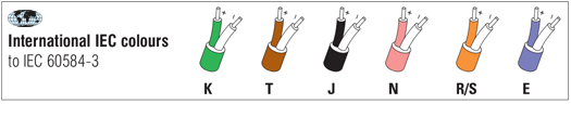
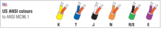
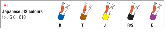
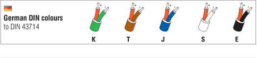
Thermocouple Cable Colour Codes
Colour identification follows IEC 60584-3: negative legs are white, positive legs follow the designated chart, and outer sheaths match the positive leg colour — except for intrinsically safe circuits, where blue sheaths are mandatory.
Thermocouple Cable Colours - at a Glance
Summary
IEC 60584-3 outlines the standards for thermocouple extension and compensating cables, focusing on identification, tolerances, and colour codes. Extension cables are marked with an 'X' and compensating cables with a 'C', with specific tolerances defined for each type. Tolerances specify the additional error introduced by the cable, and colour codes ensure proper identification of cable types and temperature ranges.
Note: The information in this guide is provided for general informational and educational purposes only. While we aim for accuracy, all data, examples, and recommendations are provided “as is” without warranty of any kind. Standards, specifications, and best practices may change over time, so always confirm current requirements before use.
Need help or have a question? We’re here to assist — feel free to contact us.
Further Reading
What is a thermocouple and how does it work?
Discover the working principles of thermocouples and how they generate EMF.
What is a PRT?
Explore how PRTs (RTD / Pt100) sensors work and the common styles
How to calibrate thermocouples
Read about the various methods of calibrating a thermocouple.