
 France
 Germany
 Spain
Spain Netherlands
 Italy
Italy Hungary
 United States
 Australia
Thermocouple Cables - Operating Characteristics
Contents
Thermocouple Cable Characteristics
In many thermocouple installations, it is necessary to run a long cable between the sensing point and remote measurement or reference equipment. However, using high-grade thermocouple wire over the full length can be unnecessarily expensive and cumbersome. Ideally, we want to connect a more economical cable that won’t compromise the measurement accuracy, while still adhering to the standard thermocouple practice of only considering the temperatures at the hot junction and the reference junction.
To achieve this, the additional cable must have thermoelectric characteristics that closely match the thermocouple's own. Extension and compensating cables are designed for this very purpose. Each offers a practical solution with different trade-offs in terms of accuracy, cost, and operating range.
Extension cables are made with the same metal conductors as the thermocouple they are designed for. As a result, they offer similar thermoelectric characteristics and minimize mismatch errors - even if junction boxes or intermediate connections are exposed to varying ambient temperatures.
While more affordable than full thermocouple wire, extension cables still carry a moderate cost. They are typically available in flexible or multi-core formats suitable for long runs and are recommended for the best accuracy.
Compensating cables are a more economical alternative. Instead of using identical metals, they use alternative alloys with similar, but not identical, thermoelectric behavior to the thermocouple they’re paired with. This keeps costs lower, but it also means the connection point between the thermocouple and compensating cable must remain within a limited temperature range. If the junction temperature drifts outside this range, mismatch errors increase and accuracy is compromised.
Compensating cable is particularly useful for extending expensive thermocouple types, such as platinum-based sensors or heavy-gauge thermocouples used in industrial furnaces or nuclear environments. In these cases, compensating cables offer a lightweight, low-cost solution that simplifies installation without sacrificing too much accuracy - provided environmental conditions are controlled.
A common example is the use of Cu vs Cu-Ni compensating cable with a Type K thermocouple at low temperatures. Since copper is already one of the conductors, the number of reference junctions is reduced, simplifying wiring for multi-point measurement setups. These cables also tend to have lower loop resistance compared to standard Type K extension wire.
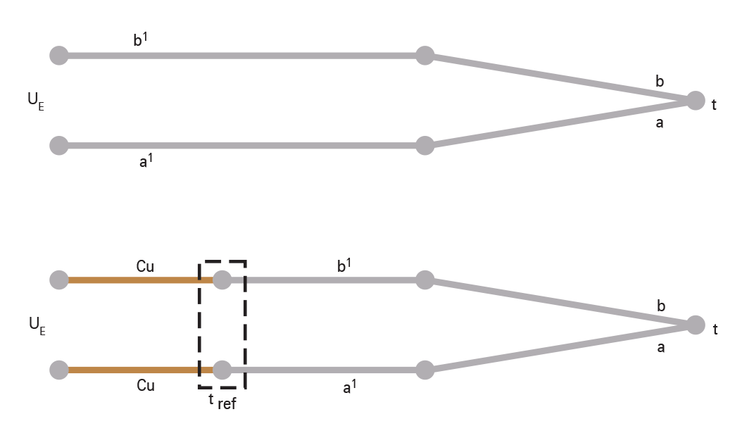
Figure 3.1: Connection of Extension or Compensating Cable
⚠️ Note: To avoid temperature measurement errors, it's critical to ensure the junction box or connection point where the thermocouple and compensating cable meet remains within the specified temperature tolerance range. If the temperature drifts outside this range, thermoelectric mismatch can distort the output.
Lead Resistance
To ensure signal quality over long runs, it’s important to consider loop resistance. Manufacturers provide resistance values for extension and compensating cables specific to each thermocouple type. These values are usually expressed in ohms per metre for a twin cable run and are calculated using a constant divided by the conductor’s cross-sectional area (see Table 3.1).
Resistance in Ohms/meter of the common thermocouple extension and compensating cable combinations at 20°C
To obtain loop resistances for twin runs per meter take the constants given below for the required combination and divide the constant by the cross sectional area in mm2 of the conductor size you intend to use.
| Code | Constant | Code | Constant | Code | Constant |
|---|---|---|---|---|---|
| KX | 1.00 | NX | 1.37 | G (W) | 0.34 |
| KCB (V) | 0.51 | RX | 0.33 | CC (W5) | 0.40 |
| TX | 0.51 | SX | 0.32 | DC (W3) | 0.38 |
| JX | 0.60 | BX | 0.39 | ||
| EX | 1.21 | RCA (U) | 0.07 |
Insulation Types
The choice of cable insulation affects both environmental suitability and installation format. Key insulation types include:
- PVC:
- Temperature range: –30°C to +105°C
- Available formats: Twisted pair, flat pair, or multi-pair
- Construction: Optional ripcords, PVC sheaths, screening, copper wire drains, or steel wire armour
- Conductor types: Solid or stranded
- PFA:
- Temperature range: –273°C to +250°C (up to 300°C short-term)
- Formats: Flat or twisted pair
- Note: No steel wire armoured versions, but stainless steel braid is optional
- Glass Fibre (Varnished & Unvarnished):
- Varnished: –50°C to +400°C
- Unvarnished: Up to +500°C (some types up to +800°C)
- Formats: Single or multi-pair in flat or twisted formats
- Optional stainless steel braiding available
Colour Coding and Specification
Extension and compensating cables are colour-coded to simplify circuit identification. While historical practices varied by region, IEC 60584-3 has established a unified international standard, now widely adopted.
Key Identification Guidelines:
- Cable Type Letters:
- 'X' suffix = Extension cable (e.g. JX)
- 'C' suffix = Compensating cable (e.g. JC)
- Class Differentiation:
- No colour distinction between Class 1 and Class 2 conductors
- Example: JX Class 1 = tighter tolerance, JX Class 2 = standard tolerance
- Colour Coding Rules:
- Varnished: –50°C to +400°C
- Negative leg = always white
- Positive leg = varies by thermocouple type (see chart on Page 5)
- Sheath colour = same as the positive leg, unless used in intrinsically safe systems, where it must be blue regardless of type
Summary
Extension and compensating cables allow thermocouples to be connected over long distances without the cost of full-spec thermocouple wire. Extension cables use the same conductors as the thermocouple, offering high accuracy and minimal thermal mismatch. Compensating cables use similar, lower-cost alloys and are suitable for less critical applications or when using expensive or bulky thermocouples. However, their accuracy depends on maintaining stable temperatures at junction points.
Cable resistance is calculated using standard loop resistance values, determined per metre and based on conductor size. A wide range of insulation types is available depending on temperature requirements—from PVC for general use to PFA and glass fibre for high-temperature environments. Finally, all cables follow international colour coding standards (IEC 60584-3), with clear markings to differentiate thermocouple types and tolerances, ensuring easy identification and consistent installation practices.
Note: The information in this guide is provided for general informational and educational purposes only. While we aim for accuracy, all data, examples, and recommendations are provided “as is” without warranty of any kind. Standards, specifications, and best practices may change over time, so always confirm current requirements before use.
Need help or have a question? We’re here to assist — feel free to contact us.
Further Reading
What are the various thermocouple types?
Explore the features and characteristics of the various thermocouple types
Thermocouple Output Tables
View EMF versus Temperature tables for all thermocouple types.
What are the thermocouple colour codes?
Explore thermocouple colour codes for cable and connectors.