
 France
 Germany
 Spain
Spain Netherlands
 Italy
Italy Hungary
 United States
 Australia
Measuring RTD Output: Application Methods and Equipment
Contents
RTDs (Resistance Temperature Detectors) produce higher signal levels than thermocouples, making them ideal for high-accuracy industrial temperature monitoring. For example, a 100 Ω Pt100 driven at 1 mA changes by ~0.385 Ω/°C (IEC 60751), which is ~0.385 mV/°C (about 3.85 mV per 10 °C). By comparison, a Type K thermocouple is ~41 µV/°C near room temperature.
Accurate temperature sensing depends on precise resistance measurement, achieved by either:
- Bridge circuits (voltage imbalance across a reference network)
- Potentiometric methods (measuring voltage across a known current source)
Bridge Measurement Systems
Bridge circuits, such as the Wheatstone bridge, compare the RTD's resistance to known resistors. The voltage imbalance correlates with temperature.
-
Two main types:
- Balanced Bridges: Used in labs; the bridge is manually or electronically rebalanced.
- Fixed Bridges: Widely used in industrial settings; the imbalance voltage is amplified and scaled to temperature.
RTD Wiring Configurations
Modern instruments are built to handle thermocouple signals more reliably, accurately, and flexibly.
Two-Wire RTD
- Simplest method.
- Lead wire resistance adds error.
- Suitable for short runs (<100 m).
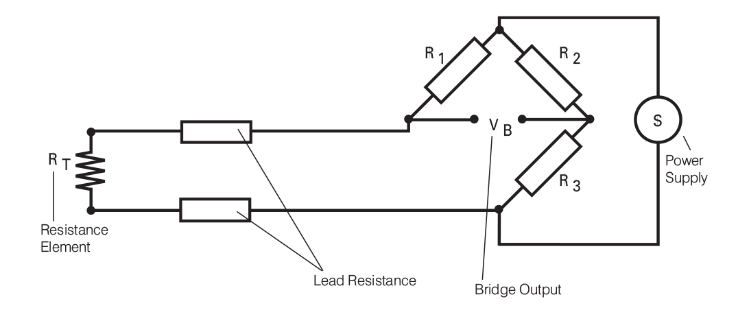
Figure 3.1: Two-Wire RTD Bridge Setup
Three-Wire RTD
- Standard in industrial applications.
- Assumes matched lead wires; cancels resistance error.
- Good for up to 500 m runs.
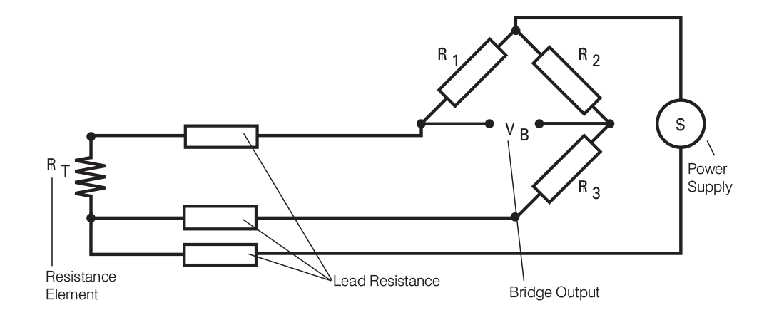
Figure 3.2: Three-Wire RTD Bridge Setup
Four-Wire RTD
- Highest accuracy.
- Fully compensates for lead resistance.
- Ideal for long cable runs (up to 1 km).
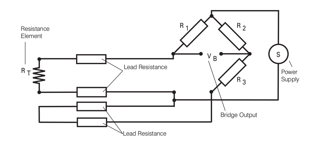
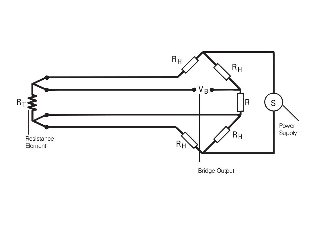
Figures 3.3 and 3.4: Four-Wire RTD Wiring Options
Measuring Differential Temperatures
Measure the difference between two locations using:
- Two RTDs in opposing bridge arms.
- Four-wire setup preferred for precision.
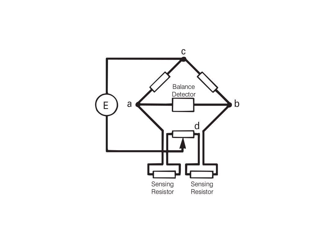
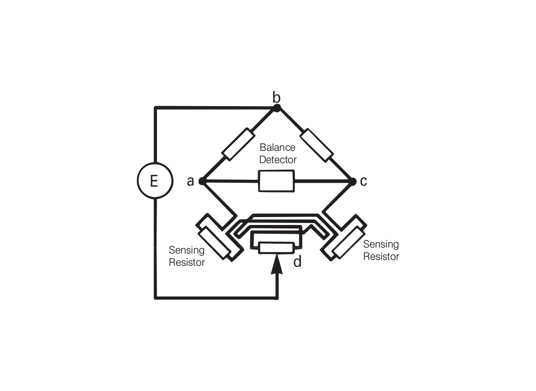
Figures 3.5 and 3.6: Differential RTD Configurations
Potentiometric (Direct Reading) Methods
An alternative to bridge circuits is a direct-reading method using a constant current source and voltmeter:
- RTD is energized with a stable, known current.
- Voltage across the sensor is measured with a high-impedance meter (minimizing loading errors).
- Lead wire resistance and switch contact resistance have negligible effect.
- Multiple RTDs can be connected in series to share the same current source.
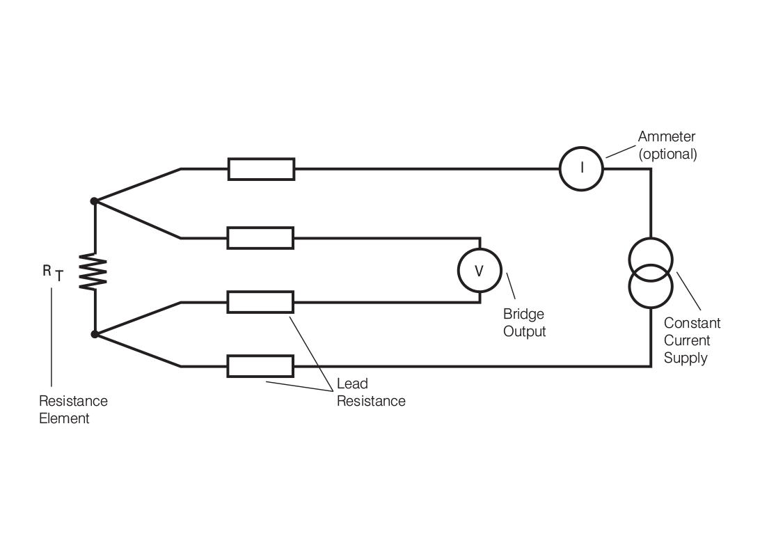
Figures 3.7: Potentiometric Four-Wire Setup
Modern Instrumentation for RTDs
Contemporary RTD systems offer simplified, accurate readings:
- Digital Indicators & Recorders: Often self-balancing and linearized.
- Transmitters (4–20 mA): Improve noise immunity and long-distance signal transmission.
- Amplifiers: Provide signal conditioning for monitoring and control.
RTD Wiring Quick Reference Table
| Wiring | Accuracy | Distance | Notes |
|---|---|---|---|
| 2-wire | Low | ~100 m | Simple; includes lead resistance |
| 3-wire | Medium | ~500 m | Balanced; common in industry |
| 4-wire | High | ~1km | Full compensation; best for precision |
Note: The information in this guide is provided for general informational and educational purposes only. While we aim for accuracy, all data, examples, and recommendations are provided “as is” without warranty of any kind. Standards, specifications, and best practices may change over time, so always confirm current requirements before use.
Need help or have a question? We’re here to assist — feel free to contact us.
Further Reading
RTD vs Thermocouple – Choosing the Right Sensor
Explore the features and characteristics of thermocouples and RTDs
RTD Output Tables
View Resistance versus Temperature tables for all Pt100 sensors.
What are the RTD colour codes?
Explore RTD colour codes and wiring configurations.