
 France
 Germany
 Spain
Spain Netherlands
 Italy
Italy Hungary
 United States
 Australia
Measuring Thermocouple Output: From Legacy Techniques to Modern Instrumentation
Thermocouples generate very small voltages, typically 10–80 μV/°C, depending on the type (see Figure 2.1). This means that careful signal measurement and compensation are essential for accurate temperature readings. Over time, methods of measuring thermocouple signals have evolved from basic mechanical systems to sophisticated digital instrumentation - each with its own use case.
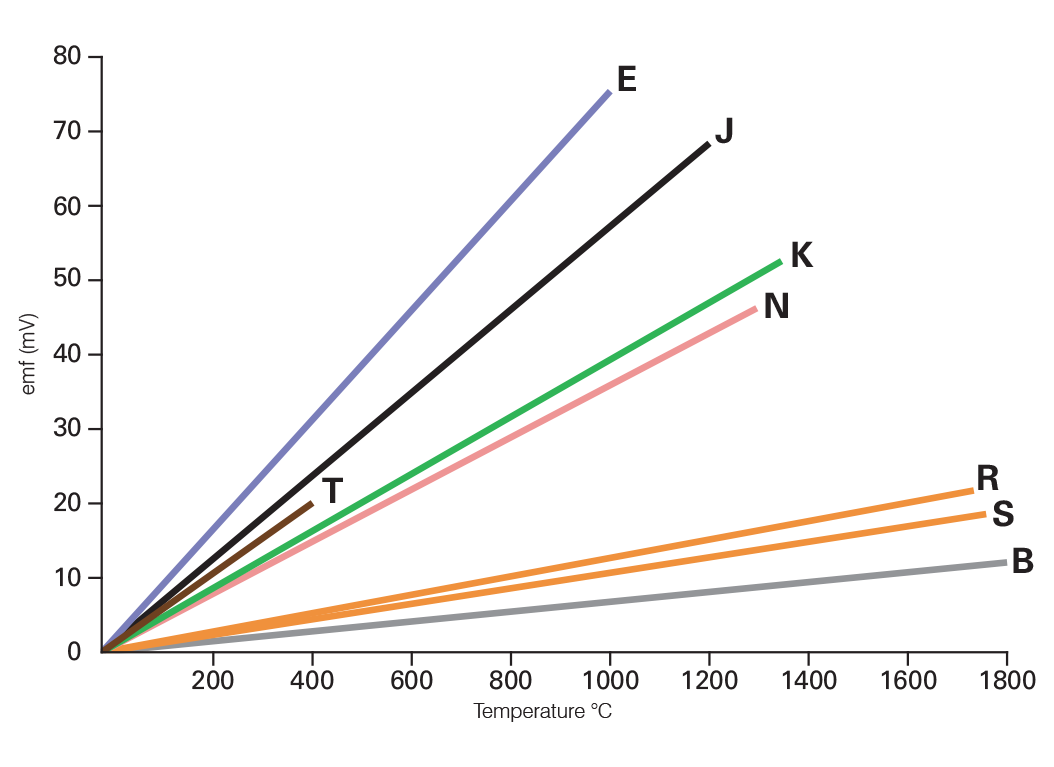
Figure 2.1: Emf vs. Temperature for Common Thermocouple Types
Legacy Measurement Methods
Understanding older techniques helps illustrate the constraints thermocouples place on measurement systems and why modern solutions have developed the way they have.
- Galvanometers and Moving-Coil Meters
In early lab and industrial setups, thermocouples were connected directly to galvanometers or moving-coil meters. These devices required no power and provided a simple, rugged way to display temperature - often on non-linear temperature scales. - Pros: Simple, low cost, power-free
- Cons: Limited accuracy, low resolution, sensitivity to circuit resistance
- Potentiometric Measurement
Null-balance potentiometers (manual or automated) measured thermocouple voltage with high accuracy by balancing it against a reference voltage. - Often used in early chart recorders
- Immune to electrical noise and ideal for laboratory use
- Still used in some rugged or portable systems today
- Zero Suppression and Offset Scaling
To improve resolution over narrow temperature spans, early systems sometimes subtracted a fixed voltage to "zoom in" on part of the thermocouple’s range. This technique (analog or digital) is now largely obsolete in favor of more precise digital methods.
Modern Thermocouple Instrumentation
Modern instruments are built to handle thermocouple signals more reliably, accurately, and flexibly.
- High-Impedance Amplifiers
Modern signal chains begin with low-noise, high-impedance amplifiers that avoid loading the thermocouple circuit. These are standard in: - Digital indicators
- Transmitters
- Data loggers
- Temperature controllers
- Temperature Transmitters
Transmitters convert thermocouple signals into robust outputs like 4–20 mA, 0–10 V, or digital signals (e.g. Modbus, HART). These are ideal for process control. - Head-mounted transmitters: Compact, sensor-integrated
- DIN rail transmitters: Modular for panels
- Smart transmitters: Include diagnostics and digital communication
- PLC and DCS Modules
Many Programmable Logic Controllers (PLCs) and Distributed Control Systems (DCSs) now support direct thermocouple input modules. - Multiple thermocouple types
- Cold junction compensation
- Built-in linearization
- Scalable and automation-ready
- Digital Indicators and Displays
Modern displays are compact, reliable, and flexible. They combine: - Cold junction compensation
- Type-specific linearization
- Multi-sensor input (e.g., K, J, T, N)
- Handheld or panel-mounted options Some can also log data, integrate alarms, or connect to networks.
- Wireless Loggers and Data Acquisition
Many industries now use wireless temperature loggers and networked acquisition systems: - Bluetooth or Wi-Fi loggers for mobile use
- Ethernet-based loggers for industrial networks
- Cloud platforms for remote access, alerts, and analysis
- Ideal for compliance, quality assurance, and multi-point monitoring
Summary: Choosing the Right Method
| Application | Suitable Method |
|---|---|
| Simple monitoring, large spans | Direct meters (legacy) |
| Lab use, high accuracy | Potentiometer or digital voltmeter |
| Industrial process control | Transmitters, PLC/DCS modules |
| Multi-point or remote logging | Wireless or networked data loggers |
| General display and diagnostics | Digital indicators |
Note: The information in this guide is provided for general informational and educational purposes only. While we aim for accuracy, all data, examples, and recommendations are provided “as is” without warranty of any kind. Standards, specifications, and best practices may change over time, so always confirm current requirements before use.
Need help or have a question? We’re here to assist — feel free to contact us.
Further Reading
RTD vs Thermocouple – Choosing the Right Sensor
Explore the features and characteristics of thermocouples and RTDs
Thermocouple Output Tables
View EMF versus Temperature tables for all thermocouple types.
What are the thermocouple colour codes?
Explore thermocouple colour codes for cable and connectors.