
 France
 Germany
 Spain
Spain Netherlands
 Italy
Italy Hungary
 United States
 Australia
Thermocouple and RTD Calibration
Contents
Accurate temperature measurement depends on well-calibrated sensors. Over time, both thermocouples and resistance thermometers (RTDs) can drift from their original specifications due to various factors like aging, contamination, or mechanical stress. This section explains how calibration works, how sensors can degrade, and what methods are used to ensure measurement accuracy.
Thermocouple Calibration
Thermocouple wires are manufactured to meet standard tolerance limits, typically defined by international standards. For example:
- Type R/S: ±1°C at the melting point of gold
- Type K: ±7.5°C at 1,000°C
Tighter tolerance wires are available for high-accuracy applications, and the same applies to extension and compensating cables. However, these tolerances apply only to new, unused sensors.
Thermocouple wire—particularly insulated or MIMS (Mineral Insulated Metal Sheathed) types—can vary in calibration along a reel. A variation of more than 1°C from one end to the other is not unusual (see Fig. 8.1).
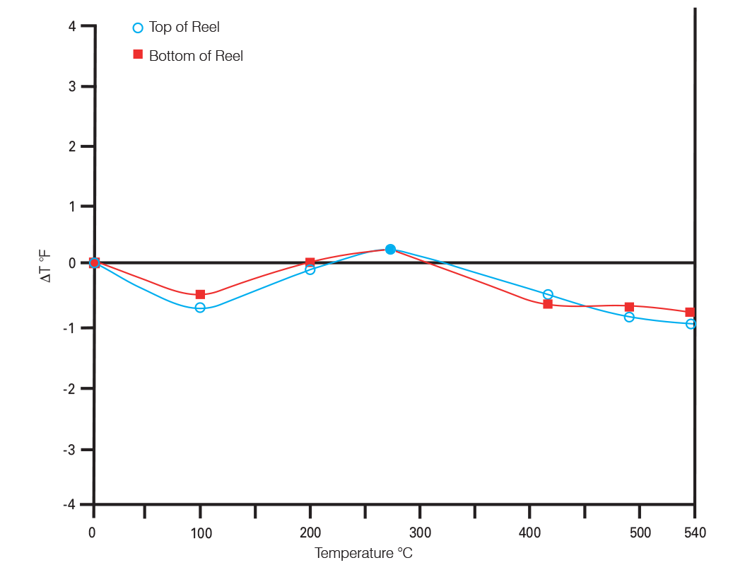
Figure 8.1: Calibration of Glass Insulated Thermocouple at Top and Bottom Ends of the Reel
Common Degradation Issues
With use, thermocouples can degrade due to:
- Insulation resistance breakdown
- Thermoelectric inhomogeneity
- Junction deterioration
These can all affect calibration stability over time.
Resistance Thermometer (RTD) Calibration
RTD elements are manufactured with extreme precision. Tolerances apply to the complete sensor, in accordance with IEC 60751, which defines two common tolerance classes:
- Class A: ±0.06Ω (≈±0.15°C) at 0°C
- Class B: ±0.12Ω (≈±0.3°C) at 0°C
RTDs generally maintain calibration better than thermocouples due to their inherent stability. However, tolerances still apply only to new sensors. Calibration checks are typically only needed if high accuracy is essential or if misuse is suspected (e.g., overheating).
RTD Degradation Causes
- Oxidation or chemical contamination
- Mechanical strain or shock
- Insulation resistance loss
- Thermoelectric effects from poor installation
- Lead wire resistance imbalance
Real-World Drift Example
In a comparative test:
- 126 RTDs were monitored over two years.
- 63 drifted more than 0.1°C
- 46 drifted up to 1°C
- 17 showed extreme drift or failed completely
- 66 thermocouples tested over six months
- All drifted by at least 1.4°C
- One drifted as much as 9.9°C
No predictable pattern of drift was observed.
Achieving Higher Accuracy
For critical measurements, calibrating thermocouples or RTDs against known temperature references is essential. Calibration may involve just a few fixed points or multiple points across the sensor's range. A correction table or curve can then be developed.
Calibration Methods
Calibration is usually done in laboratories using comparison against reference thermometers traceable to ITS-90 standards. The method depends on temperature range:
| Temperature Range | Preferred Method | Reference Instrument |
|---|---|---|
| -150°C to +250°C | Stirred liquid baths (acetone, water, oil) | Platinum RTDs |
| Up to 550°C | Salt baths (NaNO₂, KNO₃) | Platinum RTDs or rare metal thermocouples |
| Up to 1,000°C | Fluidized sand baths | Platinum-rhodium thermocouples |
| Above 600°C | Horizontal tube furnaces | Pt-Rh thermocouples or radiation pyrometers |
| Fixed-point calibration | Metal melting points (e.g., Zn, Ag, Au) | EMF observed during melting |
Important: Always ensure full immersion of the sensor and remove it from protective sheaths when possible.
In-Situ Calibration
For large, in-service thermocouples and RTDs, in-situ calibration is often more practical. A calibrated reference sensor is inserted alongside the sensor under test, and readings are compared across relevant temperatures.
RTD Checks
RTD resistance at 0°C (R₀) is a strong indicator of calibration stability. A shift in R₀ can mean:
- Strain-induced resistance — correctable via annealing
- Oxidation — can be reversed with heat treatment (450°C–550°C)
- Contamination — typically irreversible; requires recalibration
Standard method for R₀ testing: Measure resistance at the triple point of water. This enables tracking of resistance ratio rather than absolute resistance.
Achievable Accuracy
Thermocouples:
- Type R/S/B: ±0.3°C up to 1,100°C; ±2°C up to 1,550°C
- Type K/N (base metals): ±0.1°C between -80°C and +100°C; higher errors at elevated temperatures due to instability
RTDs:
- Calibration within hundredths or even thousandths of a degree is achievable for high-grade units
- Industrial RTDs can achieve:
- ±0.01% accuracy over full range
- ±0.005% stability per year for wire-wound sensors
Calibration Challenges
Thermocouples:
Thermoelectric voltage is generated along the length where temperature gradients exist. Calibration assumes uniform conductor properties, which may not hold true for aged sensors. Drift can occur even if junction temperatures remain the same (see Fig. 8.3).
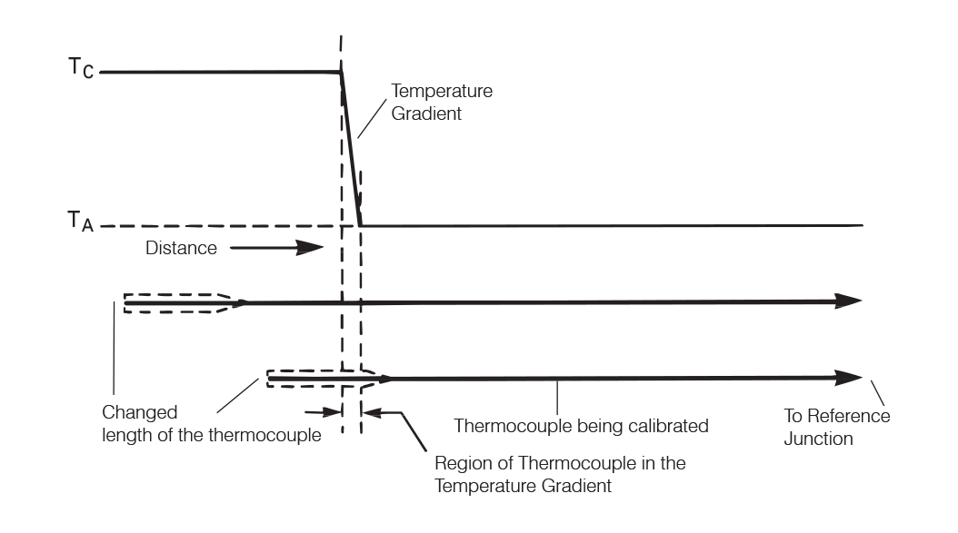
Figure 8.3: The effects of time and exposure on some thermocouples
RTDs:
RTDs are stem-sensitive, not tip-sensitive. Calibration must ensure sufficient immersion in an isothermal zone. Over time, exposure to extreme conditions can cause non-uniform aging along the sensor length, making lab recalibration potentially unreliable.
Summary
Thermocouples and RTDs are manufactured to tight tolerances, but real-world use can cause drift due to insulation breakdown, mechanical damage, or chemical exposure. RTDs generally offer better long-term stability than thermocouples. Regular calibration—either in a lab or in-situ—is essential for high-accuracy applications. Techniques range from simple reference comparisons to fixed-point calibrations traceable to international standards. Understanding how and when sensors degrade helps determine the right calibration schedule and ensures continued measurement reliability.
Note: The information in this guide is provided for general informational and educational purposes only. While we aim for accuracy, all data, examples, and recommendations are provided “as is” without warranty of any kind. Standards, specifications, and best practices may change over time, so always confirm current requirements before use.
Need help or have a question? We’re here to assist — feel free to contact us.
Further Reading
RTD vs Thermocouple – Choosing the Right Sensor
Explore the features and characteristics of thermocouples and RTDs
RTD Output Tables
View Resistance versus Temperature tables for all Pt100 sensors.
What are the RTD colour codes?
Explore RTD colour codes and wiring configurations.